Hope Needs Action
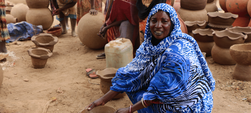
Right now, the world’s poorest are bearing the brunt of climate catastrophes. But we believe that where there's action, there's hope.
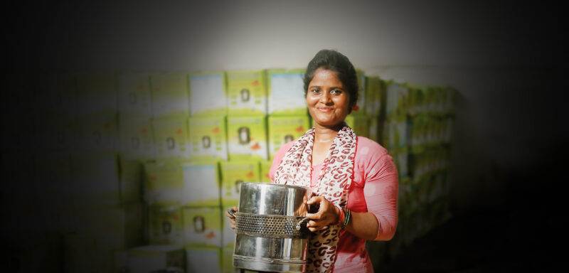
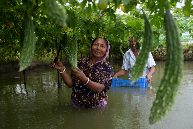
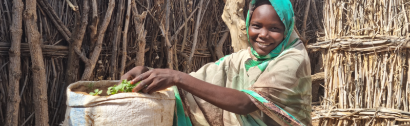
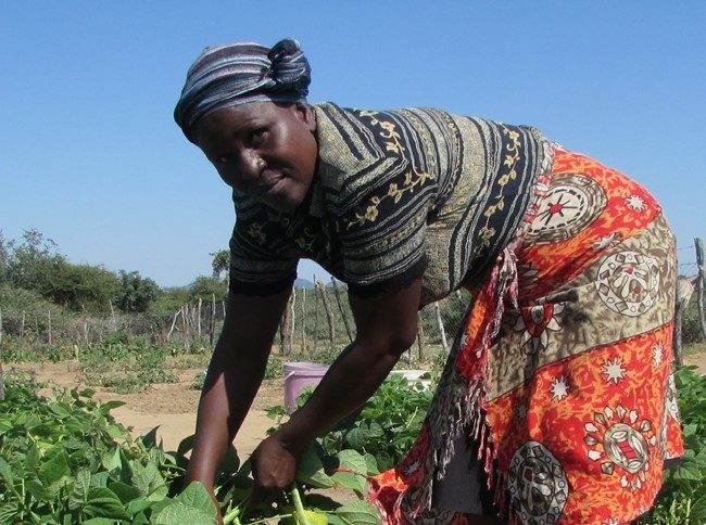
Read the full storyImproving agriculture for smallholder farmers, to adapt to climate change and improve their standard of living.
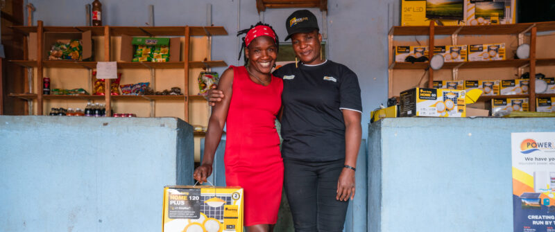
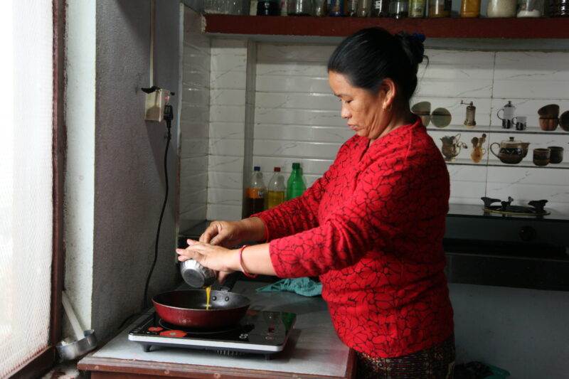
Helping people access clean affordable energy while preventing deaths from indoor stoves and fires.
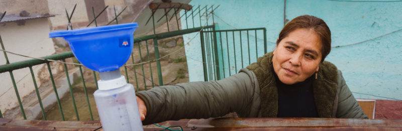
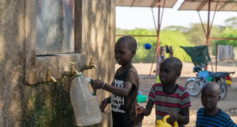
Clean water, proper waste disposal and sewage treatment for healthier living and working conditions.
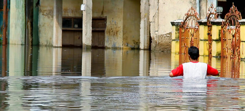
Predicting and preparing for natural hazards with communities, minimising impact on lives and livelihoods.

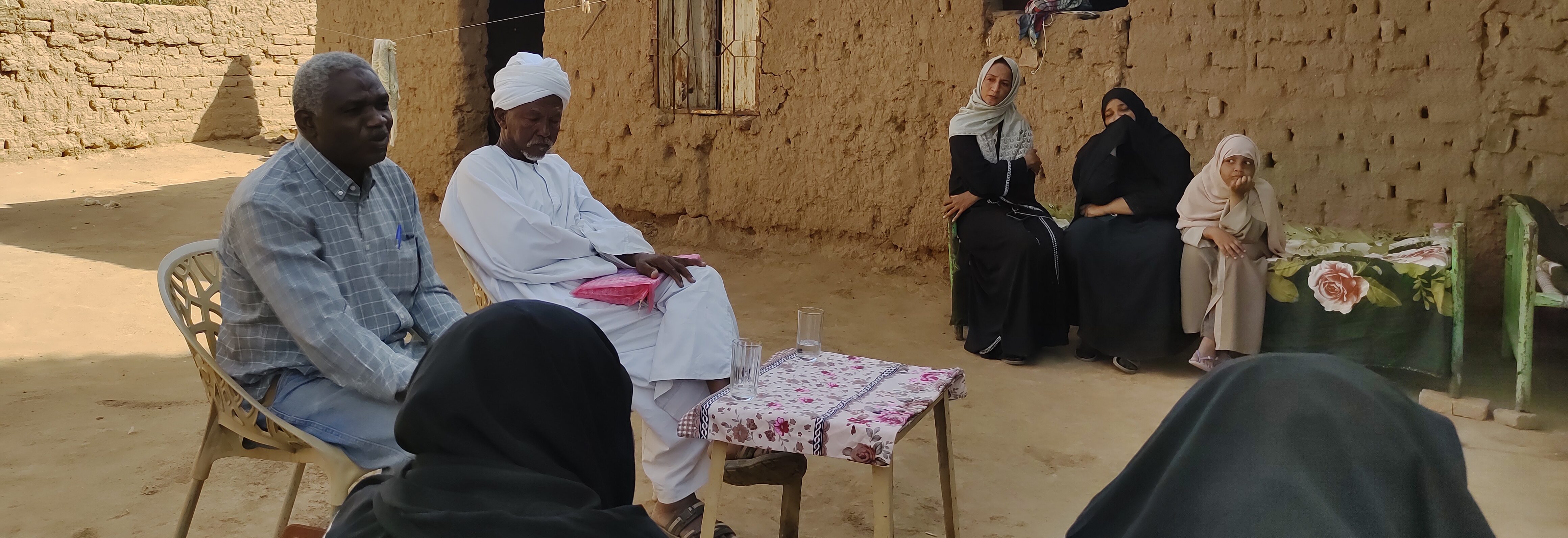
We inform policy making at global, national and local levels so that decisions made are of maximum benefit to the poorest and most vulnerable people.

We provide technical assistance to development practioners, national and local governments and the private sector.

We partner with the brightest minds to publish the latest development perspectives to practitioners and researchers in over 100 countries.

Our free, downloadable teaching resources for primary and secondary schools inspire pupils to learn about global issues.
Your gift will support people around the world in tackling their toughest challenges. Please give whatever you can. Thank you.
Our founder was radical economist and philosopher E.F. ‘Fritz’ Schumacher, a visionary who challenged the aid policies of the day. In today’s increasingly divided world suffering from catastrophic climate change, the ideas of Fritz Schumacher chime as loud as ever.
Find out moreis spent on our charitable activities around
the world.
is spent on fundraising.
There are many different ways in which you can help. Explore how you can get involved in helping people change their world.
Find out moreWe want every one of our team members to be able to make their greatest contribution to our collective effort. Check out our latest opportunities.
Find out moreWe believe in cross-sector collaborations – ones that bring together human ingenuity and innovation to change systems and create a fairer, sustainable future.
Find out moreSubscribe to Small Talk, our email newsletter, to stay updated on the big issues and how our innovative work is helping people to tackle some of the world’s toughest challenges.
We’ll also keep you updated on our supporter events, fundraising activities and the many ways you can get involved in our work.
If you are happy for us to provide information about our work, fundraising activities and ways to get involved by email please provide your details.
We take protecting your personal information seriously. We will never sell or swap your details with another organisation. We aim to provide you with a great experience of Practical Action and to communicate with every supporter in the best way possible. To do this, we may analyse your data and obtain further information about interests, preferences and level of potential donations using publicly available sources. We sometimes ask carefully selected companies to do this for us.
You can find out more about how we collect and use your personal information by reading our privacy notice at www.practicalaction.org/privacy. To change how we manage your personal information or opt out of receiving communications from Practical Action call us on 0800 389 1624 email [email protected]